MicroZed Chronicles: Avnet K24 I/O Development Kit.
- Jul 31, 2024
- 4 min read
Updated: Jun 25, 2025
Regular readers will know I am big fan of the System of Module approach, we design many into systems and solution for out clients and if necessary create similar type approaches e.g. our recent Spartan 7 Tile.
One of the great things about SoMs is the ability to hit the ground and start retiring technical risk on the development on day one while knowing the actual devices, memory etc will not change even if the IO does to some extent. This is possible as most SoM come with at least one carrier card which provides a range of interfaces which can be used for development. Some carrier card are developed with a specific purpose in mind e.g. Robotics, Vision, or Motor control while others are created to support generic interfaces.

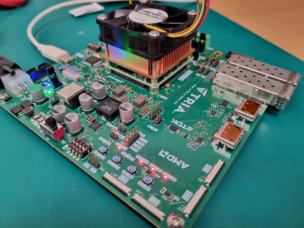
Recently Avnet announced the a new K24 IO development kit for the AMD K24 SoM. This carrier card provided developers a range of interfaces which can be used for a variety of applications.
The K24 I/O development kit includes the following
Two MikroE Click Interfaces.
Pmod Interface.
Two HSIO TXR2 Expansion interfaces.
10/100/1000 Ethernet.
USB 2.0USB C USB TAG / UART.
RGB and Standard LEDs.
Push Button and Slide switches.
SD Card and configuration boot selection.
As the K24 is based around the MPSoC with associated LPDDR4, 32GB eMMC, and 512Mb QSPI combined with the I/O development kit we are presented with a compact and capable development platform.
Getting started with an example application I am going to create a simple embedded Linux OS running on the board. As that demonstrates both the Vivado build and the PetaLinux project creation.
The first thing we need to do is create a new project in Vivado targeting the K24 SoM.

Once this is completed we need to add in the Zynq MPSoC processing system, and two GPIO which are connected to the PL LED and the RGB LEDs. The block automation should be connect the AXI and reset network we require.

The final stage is to implement enable PL to PS interrupts and connect a concat block which connects the interrupts from the two GPIO modules to the processor interrupt input.
Before we can build the design however we need to set the constraint for the PL LED and RGB LED the constraints can be seen below.
set_property PACKAGE_PIN J4 [get_ports {pl_led_out_tri_o[0]}]; # HPA23_Pset_property PACKAGE_PIN K4 [get_ports {pl_led_out_tri_o[1]}]; # HPA23_Nset_property IOSTANDARD LVCMOS18 [get_ports {pl_led_out_tri_o[*]}];set_property PACKAGE_PIN L6 [get_ports {pl_rgb_out_tri_o[0]}]; # HPA25set_property PACKAGE_PIN F4 [get_ports {pl_rgb_out_tri_o[1]}]; # HPA26set_property PACKAGE_PIN B2 [get_ports {pl_rgb_out_tri_o[2]}]; # HPA27set_property IOSTANDARD LVCMOS18 [get_ports {pl_rgb_out_tri_o[*]}];We can then create the HDL wrapper, generate the bit stream and export the XSA to our petalinux development environment.
Inside the Petalinux development machine, a Ubuntu based Linux desktop, we are able to create the project using the command
petalinux-create -t project -n k24_iocc --template zynqMPThis creates a base project for the ZynqMP processor template, once the project is open we need to cd into the project directory and customise the project for our hardware.
We do this by using the command
petalinux-config --get-hw-description=/home/adiuvo/petalinux_projects/k24IOCCWhich points to the directory which contains the exported XSA.

As this a simple project to check the embedded Linux boots etc. we can keep the settings unchanged in the system configuration. This will provide us with a ram disk file system and all necessary infrastructure to boot the embedded Linux OS.
The penultimate stage is to build embedded Linux with the command
petalinux-buildThis might take a few minutes but once it is built we have all the necessary elements to boot and operate with the embedded Linux OS.
The ultimate stage is to package the fsbl, uboot, and FPGA bit stream into a boot.bin which can be booted from our SD Card. We can do this with the command below.
petalinux-package --boot --fsbl zynqmp_fsbl.elf --u-boot u-boot.elf --pmufw pmufw.elf --fpga system.bit –force
Copying the Boot.bin, boot.scr and image.ub onto the SD Card will enable us to boot the embedded Linux OS and start exploring the K24 on the Avnet IO developer kit.


I am looking forward to doing more with this board as it is compact and presents a nice I/O expansion capability to access the K24s IO. I suspect it will feature in a few Hackster projects in the near future.
Workshops and Webinars
If you enjoyed the blog why not take a look at the free webinars, workshops and training courses we have created over the years. Highlights include
Professional PYNQ Learn how to use PYNQ in your developments
Introduction to Vivado learn how to use AMD Vivado
Ultra96, MiniZed & ZU1 three day course looking at HW, SW and PetaLinux
Arty Z7-20 Class looking at HW, SW and PetaLinux
Mastering MicroBlaze learn how to create MicroBlaze solutions
HLS Hero Workshop learn how to create High Level Synthesis based solutions
Perfecting Petalinux learn how to create and work with PetaLinux OS
Boards
Get an Adiuvo development board
Adiuvo Spartan 7 / RPi 2040 Embedded System Development Board
Embedded System Book
Do you want to know more about designing embedded systems from scratch? Check out our book on creating embedded systems. This book will walk you through all the stages of requirements, architecture, component selection, schematics, layout, and FPGA / software design. We designed and manufactured the board at the heart of the book! The schematics and layout are available in Altium here Learn more about the board (see previous blogs on Bring up, DDR validation, USB, Sensors) and view the schematics here.


