
MicroZed Chronicles: Configuring Zynq on a Custom Board
- Mar 4, 2021
- 3 min read
Updated: Jun 27, 2025
You may have seen my previous posts referencing a book I’ve been writing over the last two years with Dan Binnun and Saket Srivastava on how to design embedded systems. When we set out on this journey, we decided we wouldn’t just write about how to do it, we would also design and implement the board at the same time.
The book will be out later this year and will cover the engineering life cycle including a requirements-to-component selection, schematics, layout, and how to develop FPGA applications and reliability calculations etc. Of course, we will be making all the design information available and there will be a dedicated site that will have significant content related to the board.
The board we designed is intended to be used for IOT smart sensor applications. It’s not a development board, but a board designed to real requirements, for a real application. So, let’s take a look at what we have on the board.
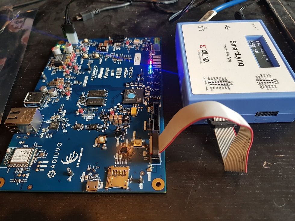
At the heart of the board, we have a Zynq-7020 SoC supported by 1 GB of DDR3 and 128 Mb QSPI configuration memory. The board also has support for SD Card boot which will be useful if we port PYNQ to it. The board provides the following sensors:
Onboard three axis accelerometer
Onboard FLIR Lepton 3 thermal sensor
Onboard vibration sensor
Onboard eCompass for magnetic field detection
On board temperature and humidity
Remote temperature sensing
Remote humidity sensor
Of course, we also have a range of communication interfaces well suited for its IOT application.
1G Ethernet
WiFi
Bluetooth
USB host
USB UART for debugging
We recently got the boards back from the manufacturer so I want to talk a little about how to bring up a new custom Zynq board here. We’ll start with how to configure the PS side of the device so that it will interface correctly with the peripherals and most importantly, correctly configure the DDR and clocking.
When we work with a custom Zynq board, we don’t get the ability to run the block automation out of the box so we have to create those files first.
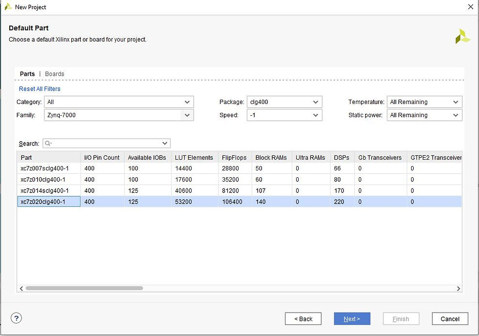
This is where the fun begins so let’s take a look at how we can do that. The first thing we need to do is create a new project targeting the Zynq device. For this exercise, we’ll use a Zynq XC7Z020CLG400-1.
Once the project is created, the next step is to create a block diagram and add in a Zynq processing system.
To configure the PS correctly for a custom board, you are going to either need a previous pin planning project or the schematics, along with some trace information on the DDR from the layout.
The first step is to configure the MIO as required for the board. Here you need to connect the UART, SPI, USB and GigE interfaces as they are connected on your board.

Once the MIO has been correctly populated, the next step is to set up the clocking. We used a 50 MHz oscillator on this custom board.

With the base set up, the clock frequency is 650 MHz but we can achieve the full 666.66’ MHz by setting the clock override on the advanced clocking tab and adjusting the first divider and the ARMPLL multiplier.

The final stage before we can create a project is to configure the DDR memory. This is where we need a little information on the layput of the PCB.
We need to enter the component selected, its configuration on the board (e.g. effective bus width), temperature range, and beat cycles in this window.
We also need to know the board delays for the DQS to clock and DQS average delays from the layout.
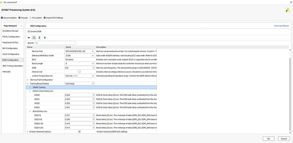
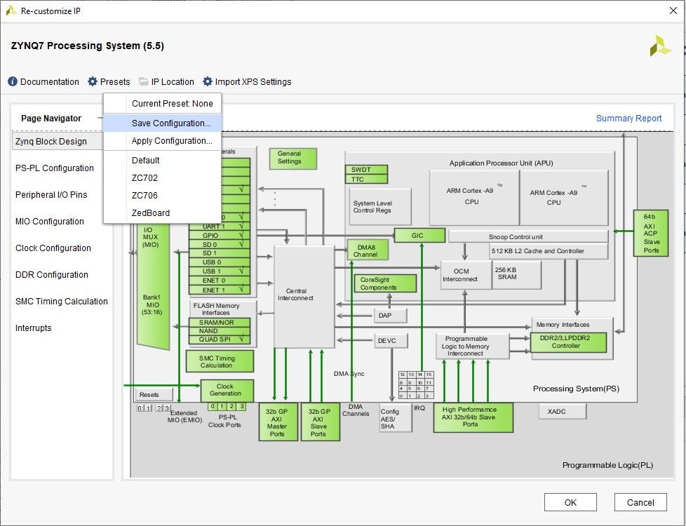
Once all these are entered, we can save the configuration to a TCL file so that we do not need to re-enter this data at every step.
You can save the configuration by clicking on the Presets and selecting Save Configuration. This will allow you to save a TCL file that can be used to apply the configuration to a new project at a later point in time.
Now we know the basic steps involved in configuring a processing system for a custom board. In the next blog, I will demonstrate how we can test this and the hardware at the same time to help determine if the system is working correctly.


