
MicroZed Chronicles: Introducing Vitis Unified IDE
- Nov 1, 2023
- 6 min read
Updated: Jun 25, 2025
If you’ve been working with Vitis 2023.1, you’ll already be aware that a new Vitis Unified Integrated Design Environment (IDE) was scheduled for released with the next version of Vitis. Vitis 2023.2 was released earlier this month and along with it, the new Vitis Unified IDE. Here, we’ll take a look at the new Vitis Unified IDE.
The Vitis Unified IDE is designed to combine what was previously several different tools. As such, it combines Vitis IDE, Vitis HLS, and Vitis Analyzer into a single tool. Using this tool, we are able to develop embedded applications for Versal, Zynq MPSoCs, and Zynq devices along with MicroBlaze CPUs. We are also able to create system projects for acceleration on SoCs and accelerator cards in addition to creating HLS applications and developing AI engine applications and kernels.
To get started, we are going to take a walk through the creation of a simple project using the embedded development flow. It’s pretty straight forward and similar to the original Vitis (now Vitis Classic), however, there are a few differences.
For this project I am going to get started with a simple design which targets the Avnet ZUBoard and implements a simple MPSoC instantiation connected to an AXI GPIO which drives the LEDs on board connected to the PL. This allows me to show one of the major differences introduced with the Vitis Unified IDE.

When the Vivado project is complete, we are able to generate the bitstream and export the XSA as we have always done. Just as before, we can open the Vitis Unified IDE from the Vivado tools menu.
Once the Vitis Unified IDE is open, you will see it looks different to the eclipse-based classic Vitis IDE. Vitis Unified IDE looks very similar to the VS Code but with a lot more functionality to support AMD programmable devices.

The flow for creating an embedded project is as follows:
Create or open a workspace
Create the platform targeting the XSA or use an existing in-built platform
Create the embedded application from either a blank project or use an existing template
All of this is very similar to the previous flow; however, the exact steps vary slightly.
The first thing we will do is create a workspace which requires us to select the directory we wish to work within.
With the workspace opened, we are then able to create a platform based of our XSA. To do this, select create platform component and work through the dialog. Then name the component and select the component location.

With the component name and location entered, the next step is to identify the XSA we wish to use.

Then select the operating system and the processor to run the applications on.

Since we are targeting a bare metal development, the platform can be created once this has been completed.

Explore the created platform and you will see artefacts similar to what is present in Vitis Classic. The first element is the summary of the platform and shows the boot objects and standalone elements.

Exploring the standalone application BSP, you will see the customization elements for the BSP including the BSP libraries, compilation options, and standalone BSP options such as Stdin/Stdout etc. along with library and driver configurations.


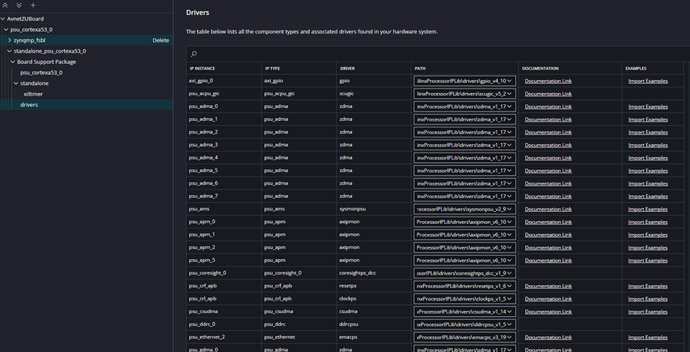
One of the big differences between the Vitis Unified IDE and Vitis Classic is how the xparamters.h is created and what it contains. While Vitis Classic uses HSI SPI to extract data from the XSA file, Vitis Unified IDE uses a system device tree to create several device trees which are used to describe the configuration and generate the xparameters.h file using the python looper frame work. However, the contents of the xparameters.h file are slightly different because each component declared no longer has a device ID. Of course, this changes how we instantiate the components and APIs in our embedded solution. All of the example files and APIs, however, appear to have been updated as one would expect to support both flows.
By exploring the BSP generated by the system device tree, you can see that the device ID is not provided in the xparameters.h file for the AXI GPIO. When used with the system device tree, the API has been updated to use the base address for initialization in place of the device ID instead.

You can examine the system device tree, under <platform> Sources->HW->SDT.
With the platform created, we are now in a position to be able to create the application. Here, I am going to always use a Hello World template to get us up and going.
Select examples from the welcome page, and a list of example applications will be displayed along the right side.

Select the example you desire (the Hello World example in this case) and a new tab will open which shows the supported OS, supported processors, and the required libraries. Select Create Application Component from Template and follow the dialog which opens up.

Enter the name of the application component and its location.

Select the hardware platform which is to be used for the application example. In this case, we can select the platform which was just created.

Select the domain and click next.

Select finished on the final tab.

This will create the application and show the settings for the application and associated platform.

The other major change between the Vitis Classic and Vitis Unified IDE is the removal of MSS, MDD, MLD files and the introduction of CMake and YAML-based flows. You will see the CMake, YAML and JSON files used under the settings tab for the project just created.
Under these settings, you will see the ability to manipulate the compiler settings and we can also see the run settings for working with the hardware on target.


Under these settings, you will see the ability to manipulate the compiler settings and we can also see the run settings for working with the hardware on target.

Once the application is compiled, and provided we have the ZUBoard connected and powered, we can click debug under the flow target and the application will be downloaded and made available for debugging. The system halts at the first line of the code as would be expected.

In this debug view, we are able to breakpoint and single step through the application as we normally do when working with embedded targets.

We can also observe memories, registers, and profiles just as we do with Vitis Classic.

The next thing we need to do is update the application to enable the AXI GPIO and drive out patterns to the two PL RGB LEDs.
To do this, we need to update the main application to use xparameters.h and XGpio.h. Of course xparameters provides the necessary component information and XGpio provides the functions to initialize and work with the AXI GPIO.

#include <stdio.h>
#include "platform.h"
#include "xil_printf.h"
#include "xparameters.h"
#include "xgpio.h"

XGpio LEDS;

int main()
{
    init_platform();
    print("Vitis Unified IDE Example\n\r");
    XGpio_Initialize(&LEDS, XPAR_XGPIO_0_BASEADDR);


    XGpio_SetDataDirection(&LEDS, 1, 0x0 );
    XGpio_SetDataDirection(&LEDS, 2, 0x0 );

    while(1){
        XGpio_DiscreteWrite(&LEDS, 1, 0x01);
        XGpio_DiscreteWrite(&LEDS, 2, 0x04);
        usleep(500000);
        XGpio_DiscreteWrite(&LEDS, 1, 0x02);
        XGpio_DiscreteWrite(&LEDS, 2, 0x01);
        usleep(500000);
        XGpio_DiscreteWrite(&LEDS, 1, 0x04);
        XGpio_DiscreteWrite(&LEDS, 2, 0x02);
        usleep(500000);
    }


    cleanup_platform();
    return 0;
}
The main difference is the initialization used when working with the system design tree, the base address of the component and not the ID. This can be clearly seen in the code above and running this on the hardware results in flashing LEDs as we would expect.
Of course, we will be using the Vitis Unified IDE significantly as we go forward!
Workshops and Webinars
If you enjoyed the blog why not take a look at the free webinars, workshops and training courses we have created over the years. Highlights include
Professional PYNQ Learn how to use PYNQ in your developments
Introduction to Vivado learn how to use AMD Vivado
Ultra96, MiniZed & ZU1 three day course looking at HW, SW and Petalinux
Arty Z7-20 Class looking at HW, SW and Petalinux
Mastering MicroBlaze learn how to create MicroBlaze solutions
HLS Hero Workshop learn how to create High Level Synthesis based solutions
Perfecting Petalinux learn how to create and work with petalinux OS
Embedded System Book
Do you want to know more about designing embedded systems from scratch? Check out our book on creating embedded systems. This book will walk you through all the stages of requirements, architecture, component selection, schematics, layout, and FPGA / software design. We designed and manufactured the board at the heart of the book! The schematics and layout are available in Altium here Learn more about the board (see previous blogs on Bring up, DDR validation, USB, Sensors) and view the schematics here.
Sponsored by AMD


