
MicroZed Chronicles: Dynamic Clocking
- May 17, 2023
- 4 min read
Updated: Jun 25, 2025
Clocking is at the heart of every FPGA design.. We can spend a lot less time battling the tools if we get the clock architecture right, have no CDC issues, and correctly constrain the design.

For some applications though, we want to be able to change the clock frequency in certain elements of processing pipelines. One such example is in image processing pipelines where the output resolution can change dynamically, thereby requiring the pixel clock to change.
As we know, we can use the fabric clocks and change the frequency of those at run time in Zynq SoCs and Zynq MPSoC. However, if we are using a FPGA or PL in a Zynq or ZYNQ MPSoC we can still change the frequency at run time using a clocking wizard which is configured for dynamic reconfiguration.
Dynamic reconfiguration allows us to change the clock frequency at run time by using the AXI interface which makes it ideal for pipelines that need clock frequency adjusting.

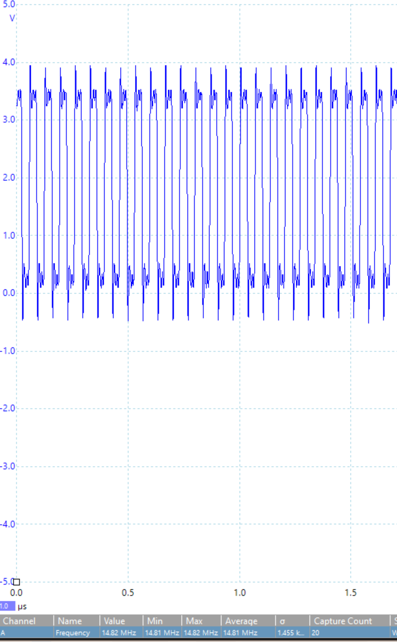
Let’s take a look at how we can get this working using a Digilent Cora Z7 board. To create a simple example, we will instantiate the processing system and connect a clock wizard to the master AXI interface from the PS. We will connect the output clock to a IO pin so that we can scope it and see the change in frequency.

When we do this, we should set the clock output in the clock wizard to the maximum frequency we intend to use to ensure that the timing constraints and timing performance are correct. See below for the final design shown in Vivado.

We will see a familiar software environment within Vitis and we will see the clock wizard and its documentation under the IP within the design.
Using the clock wizard is like any other IP in Vitis and is connected over the AXI Lite interface. The first thing to do is to configure the clocking wizard SW instantiation so that it knows the memory address of the wizard and its current capabilities.
Once this has been achieved, we are able to use the clocking wizard API to configure the output clocks. To do this, we need to write and read from the clocking wizard register space.
To change the clock frequency output, we have two options. If there is only one clock being generated, we can use a function called SetRate. This function will be passed the desired frequency output by the clock wizard and it calculates the necessary dividers, multiplication, and phase parameters to achieve the desired output frequency.
If, however, we have more than one clock, then we need to calculate these registers’ values separately and update the clock registers individually (each clock has two registers).
Once we have set the registers in the register space, in order for them to take effect we need to write to the configuration register for the changes.
It is then also good practice to wait for the clock wizard to lock to the new frequency before we continue using the effected processing pipeline.
Running this on the Cora Z7 board and changing the frequencies with the code example below was simple and straight forward.
#include <stdio.h>
#include "platform.h"
#include "xil_printf.h"

#include "xclk_wiz.h"

XClk_Wiz ClkWiz_Dynamic;
XClk_Wiz_Config *CfgPtr_Dynamic;

#define XCLK_WIZARD_DEVICE_ID		XPAR_CLK_WIZ_0_DEVICE_ID
#define XCLK_US_WIZ_RECONFIG_OFFSET	0x0000025C
#define CLK_LOCK			1

int main()
{
    init_platform();
    int Status;
    print("Hello World\n\r");

    CfgPtr_Dynamic = XClk_Wiz_LookupConfig(XCLK_WIZARD_DEVICE_ID);
	XClk_Wiz_CfgInitialize(&ClkWiz_Dynamic, CfgPtr_Dynamic,
	                       CfgPtr_Dynamic->BaseAddr);

	while(1){
		XClk_Wiz_WriteReg(CfgPtr_Dynamic->BaseAddr,
		                  XCLK_WIZ_REG25_OFFSET, 0);
		XClk_Wiz_SetRate(&ClkWiz_Dynamic, 10);
		XClk_Wiz_WriteReg(CfgPtr_Dynamic->BaseAddr,
		                   XCLK_US_WIZ_RECONFIG_OFFSET,
		                  (XCLK_WIZ_RECONFIG_LOAD |
		                  XCLK_WIZ_RECONFIG_SADDR));
		Status = XClk_Wiz_WaitForLock(&ClkWiz_Dynamic);
		usleep(10000000);
		XClk_Wiz_WriteReg(CfgPtr_Dynamic->BaseAddr,
		                  XCLK_WIZ_REG25_OFFSET, 0);
		XClk_Wiz_SetRate(&ClkWiz_Dynamic, 14);
		XClk_Wiz_WriteReg(CfgPtr_Dynamic->BaseAddr,
				         XCLK_US_WIZ_RECONFIG_OFFSET,
				        (XCLK_WIZ_RECONFIG_LOAD |
				        XCLK_WIZ_RECONFIG_SADDR));
		Status = XClk_Wiz_WaitForLock(&ClkWiz_Dynamic);
		usleep(10000000);
	}
    cleanup_platform();
    return 0;
}
Of course, we can also use approaches like this to reduce the power in the FPGA in different power modes by reducing the clock frequency to a much lower setting which also reducing power dissipation.

There are also some interesting things we can do with the PS fabric clocks which we will look at in a future blog.
Workshops and Webinars
If you enjoyed the blog why not take a look at the free webinars, workshops and training courses we have created over the years. Highlights include
Introduction to Vivado learn how to use AMD Vivado
Ultra96, MiniZed & ZU1 three day course looking at HW, SW and Petalinux
Arty Z7-20 Class looking at HW, SW and Petalinux
Mastering MicroBlaze learn how to create MicroBlaze solutions
HLS Hero Workshop learn how to create High Level Synthesis based solutions
Perfecting Petalinux learn how to create and work with petalinux OS
Embedded System Book
Do you want to know more about designing embedded systems from scratch? Check out our book on creating embedded systems. This book will walk you through all the stages of requirements, architecture, component selection, schematics, layout, and FPGA / software design. We designed and manufactured the board at the heart of the book! The schematics and layout are available in Altium here Learn more about the board (see previous blogs on Bring up, DDR validation, USB, Sensors) and view the schematics here.


