
MicroZed Chronicles: Ethernet on the Digilent Arty A7
- Jun 7, 2023
- 4 min read
Updated: Jun 25, 2025
A couple of weeks ago I was emailed about how to get the ethernet working on the Digilent Arty A7 development board. We have covered this topic in the past when we created a PetaLinux-based solution for MicroBlaze running on an Arty board, but let’s take a second look.

In this blog we are going to walk through how to get the Digilent Arty A7-35T up and running with the LWIP echo server. To do this we will be using a MicroBlaze running its application from the DDR3L attached to the Arty A7.
The LWIP is a good starting point for working with the bare metal designs and ethernet, from this base we can easily adapt the software application to provide more detailed applications. The use of the LWIP Echo server first enables us to determine the underlaying base design is working as we would expect.
At the heart of this design is the AXI Ethernet Lite IP module from the AMD IP repository within Vivado (I am using 2023.1 for this project). The AXI Ethernet Lite IP is intended for 10 or 100 Mbps Ethernet links and is very straight forward to set up and integrate within our designs. This provides a low footprint Ethernet interface, which is ideal for us in cost optimized devices like the Artix 7 FPGA on the Arty. With a simple Ethernet interface provided the designer can use Ethernet for command and control of the end application.

To create our project, I am going to target the Arty A7-35T board. Once the project is created, I will add in the following IP from the Board tab in IP Designer once I have created a block diagram

This will provide us with a nice platform which we can use to implement further modifications to the application (e.g., to read switches or set LEDs over Ethernet).
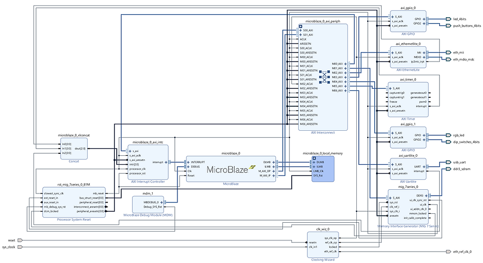
The complete design can be recreated by using the TCL script stored in the Git Repo. Key design points include the use of the DDR clock out to clock all of the AXI network except for the AXI Ethernet Lite IP block (which clocks at 100 MHz).
The DDR is clocked at 100Mhz for the system clock and 200 MHz for the reference clock. The DDR interfaces runs at 324.99 MHz and its interface is at ¼ the frequency (81.2475MHz) which is the frequency of the majority of the AXI interface.
Along with the AXI Ethernet Lite IP, we need to provide a 25MHz reference clock to configure and work correctly with the Ethernet Phy.
Once completed the design in Vivado looks like below, generate the HDL wrapper and create a bitstream.
With a bit stream available the XSA can be exported from Vivado and imported as the platform for a new application project in Vitis.
Target the MicroBlaze processor and select the LWIP Echo Server application.

With the project created you can build the application and the platform. Note, in Vitis 2023.1 when the LWIP was compiled there was an error in the xadaptor.c file, line 388 has two declarations of status as a 16 bit and 32 bit variable. Comment out the 16 bit declaration and recompile the design if this happens.
With the Arty A7 board connected to the development PC via the Ethernet connection, we can download and run the application on the Arty A7 board.
The terminal will output the IP address and provide information that all commands sent to port 7 will be echoed back.

To be able to connect to the Arty A7 over Telnet, we need to first configure the IP address of the host machine to be similar to the Arty A7.

With the IP settings on the host computer correct, we can open a Telnet session with the Arty Board and send down commands to be echoed.
It is best to set the Terminal program to perform a local echo and to append CR/LF to the messages.

We can then enter text and watch it echo back. You will notice a slight delay between sending the command and it being echoed back.

This provides us a good starting point for us to be able to start developing new Ethernet enabled projects.
Workshops and Webinars
If you enjoyed the blog why not take a look at the free webinars, workshops and training courses we have created over the years. Highlights include
Introduction to Vivado learn how to use AMD Vivado
Ultra96, MiniZed & ZU1 three day course looking at HW, SW and Petalinux
Arty Z7-20 Class looking at HW, SW and Petalinux
Mastering MicroBlaze learn how to create MicroBlaze solutions
HLS Hero Workshop learn how to create High Level Synthesis based solutions
Perfecting Petalinux learn how to create and work with petalinux OS
Embedded System Book
Do you want to know more about designing embedded systems from scratch? Check out our book on creating embedded systems. This book will walk you through all the stages of requirements, architecture, component selection, schematics, layout, and FPGA / software design. We designed and manufactured the board at the heart of the book! The schematics and layout are available in Altium here Learn more about the board (see previous blogs on Bring up, DDR validation, USB, Sensors) and view the schematics here.


