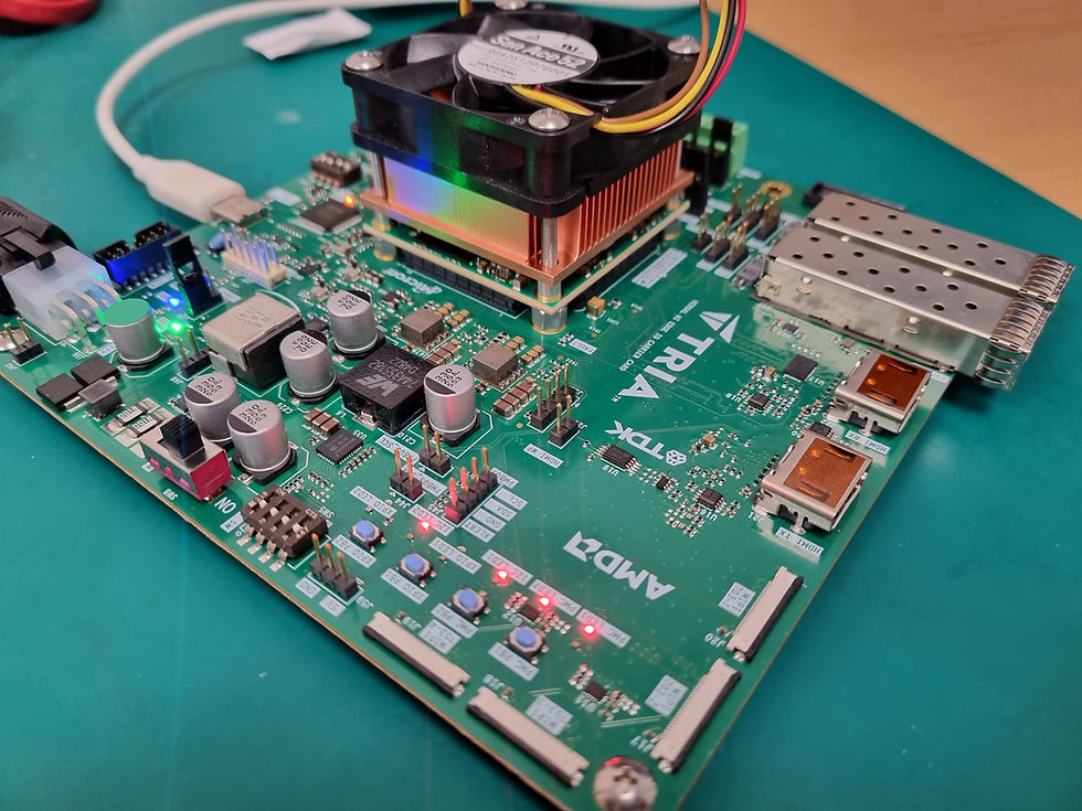
MicroZed Chronicles: Working with the Kria SOM in Vivado
- Adam Taylor

- Aug 25, 2021
- 4 min read
Updated: Jun 27, 2025
The Kria KV260 Vision AI Starter Kit is great for embedded vision applications and AI acceleration. Several of my clients, however, have expressed an interest in the SOM for applications outside of vision applications and AI or where vision / AI only forms a small part of the overall application.

Therefore, I thought it would valuable to demonstrate how a Kria SOM application can be created using Vivado and Vitis, just like we can for any other SOM or board.
This project is going to implement a simple PWM output in the programmable logic of the Kria SOM connected to the Pmod port. A similar approach would be necessary if the application required motor control or other actuator control.
To get started, the first thing we need to do is create a new project that targets the Kria SOM. I used Vivado / Vitis 2020.1 for this project.
Select the Kria KV260 Vision AI Starter Kit for the target board when creating the project. This will be available from the boards tab. Selecting this board will ensure that Vivado is aware of the target board and will be able to configure the SOM device correctly for use.
See my previous posts Getting Started With Vivado and Creating Applications with Vitis if you are not sure how to work with Vivado and Vitis for simple project flows.

Once the project has been created, the development of the Vivado application is the same as usual. Create a block diagram and add on the MPSoC (run the block automation to configure the MPSOC block for the Kria), and add in a AXI Timer. Make the PWM pin on the AXI Timer external. I gave it the name of the Kria SOM pin which is connected to the PMod pin 1.

This might raise the question about how I know which device pin on the SOM is connected to the connector and consequently to the Pmod. This information comes from the schematics that are provided by Xilinx for the Kria Vision AI carrier card.
These schematics show the Pmod pin 1 as being HDA11. This indicates it is connected to a high-density bank on the Kria device.

Here we need to use the two XDC files that Xilinx provides. The first one the carrier card XDC defines the KRIA connector number in this case som240_1_a17. The second XDC file defines the actual pin location on the device as H12. Both these XDC files and the schematics can be downloaded from the Xilinx Kria webpage
We can add both these XDC files to our Vivado project and name the IO in our design for the desired SOM connector pin. In this example, I named the PWM output port as som240_1_a17 so that it would be connected to the correct place on the actual device.
By default, the configuration of the MPSoC on the Kria does not enable a UART. Examining the schematics MIO pins 36 and 37 are used for TX and RX connected to the USB UART. We need to enable UART1 in the MPSOC device in order to be able to send out a Hello World message over the USB/UART.

Once this is completed, we can create the HDL wrapper, build the project, and export it for use in Vitis.
Using Vitis, we can pull in the exported XSA and create a new Hello World project. We can add a few simple lines of code into this project which configures the AXI Timer to produce a PWM signal with a 500 ms duty cycle and a 25% on time.
#include <stdio.h>
#include "platform.h"
#include "xil_printf.h"

#include "xtmrctr.h"

#define TMRCTR_DEVICE_ID        XPAR_TMRCTR_0_DEVICE_ID
#define PWM_PERIOD              500000000    /* PWM period in (500 ms) */
#define TMRCTR_0                0            /* Timer 0 ID */
#define TMRCTR_1                1            /* Timer 1 ID */
#define CYCLE_PER_DUTYCYCLE     10           /* Clock cycles per duty cycle */
#define MAX_DUTYCYCLE           100          /* Max duty cycle */
#define DUTYCYCLE_DIVISOR       4            /* Duty cycle Divisor */

XTmrCtr TimerCounterInst;

int main()
{
	u8  Div;
	u32 Period;
	u32 HighTime;
    init_platform();

    print("Hello World\n\r");
    print("Successfully ran Hello World application");

    XTmrCtr_Initialize(&TimerCounterInst, TMRCTR_DEVICE_ID);


    Div = DUTYCYCLE_DIVISOR;
    XTmrCtr_PwmDisable(&TimerCounterInst);
	Period = PWM_PERIOD;
	HighTime = PWM_PERIOD / Div--;
	XTmrCtr_PwmConfigure(&TimerCounterInst, Period, HighTime);
	XTmrCtr_PwmEnable(&TimerCounterInst);
	while(1){

	}

    cleanup_platform();
    return 0;
}
To run this on the Kria SOM, I connected over USB JTAG and was able to download the application and start it running using Vitis’ debugging environment.
Connecting a scope to pin 1 of the Pmod shows the image above with the correct period and positive duty cycle.
Next time we will take a look at recreating the design examples that come with the Kria!
Up Coming Book!
Do you want to know more about designing embedded systems from scratch? Check out our upcoming book on creating embedded systems. This book will walk you through all the stages of requirements, architecture, component selection, schematics, layout, and FPGA / software design.
We designed and manufactured the board at the heart of the book!
Learn more about the board (see previous blogs on Bring up, DDR validation, USB, Sensors) and view the schematics here.
See the schematics, the layout will be made available on a new website soon!


