MicroZed Chronicles: Interesting Interview Question.
I spend a lot of time reading forums and social media related to FPGA. Recently I was reading r/fpga and saw some interesting interview questions someone had been asked at a finance company.
There were two questions.
1. You have a 100 MHz reference clock and another clock with an unknown frequency. Design a circuit to measure the unknown frequency.
2. Given a one cycle input pulse, generate an output that stays high for ten clock cycles in total, the input cycle plus nine more. The output must assert immediately when the input asserts, through a combinational path, without waiting for a clock edge. How would you implement it and what assumptions would you make about the input?
Discussions on this thread were interesting so I thought I would take a shot at answering these questions. Both have some interesting points which need to be considered but I think they are standard interview questions looking more at how you think and if you know the basics.
The first question is of course open ended, we do not know if the clock to be measured is faster or slower than the reference clock. I think that might be what the interviewer is looking for, we simply do not know its frequency relationship to the reference clock so must act accordingly.
One approach is to use a gated approach, this counts the number of rising edges occurring within a window of reference clock cycles.
Using this approach, the length of the gate multiplied by the reference clock period is the gate time, with a resolution of one count.
The result has an uncertainty of around +/-1 count as we have an unknown clock edge, and the window has no phase relationship with it. Depending on where the first edge occurs the window may contain one more or one fewer count.

This is important as for a gate period of 1 ms and an unknown clock running at 125 MHz the 1 ms gate will give you around 125000 counts while +/-1 count is 8 ppm.
However, as the frequency of the unknown clock decreases the +/-1 count uncertainty becomes larger in percentage terms.
If the unknown clock is 1 MHz the uncertainty is 0.1%, however if the unknown clock frequency is 12 kHz +/-1 count is 8.3%, which makes the measurement much less useful.
There is however an even more tricky element to this challenge and that is it is only the unknown clock that can count its own cycles. We therefore need to cross clock domains from the unknown clock domain to the reference clock domain.
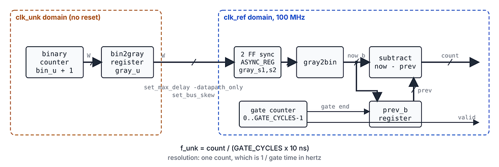
We can do this with a simple incrementing binary counter (we just need to size the counter sensibly). However we cannot easily cross a binary count from one clock domain to another (simply) using two stage flip flops when several bits of the count change, as metastability recovery variation will cause corruption.
The solution is therefore to use a Gray code counter, in Gray code only one bit changes between adjacent count values.
We can then use two stage synchronisers to synchronise the Gray count across the clock domains, taking care to constrain the skew between the Gray code bits.
We can then convert the synchronised value back to binary and work out the frequency by determining the count at the end of the window against the previous end count (the unknown counter is free running).
If we use a sensible round number for the gate we can easily work out the frequency of the signal by doing a multiplication by the scaling factor. For example with a 1 ms gate, which is 1/1000 of a second, the frequency is the count scaled by 1000.
In this approach however the entire Gray code count needs to cross the clock domains.
The simpler solution is to measure the time it takes for the unknown clock to count to a specific number.
Using this approach we can have the counter toggle an output bit when it reaches the terminal count and reset its count value.

The toggle output can be synchronised using a two stage FF in the reference clock domain. Using a simple edge detector we can reset a counter to zero. The reference clock counter then increments until it detects the next edge at which point the count is output.
This approach still has an uncertainty of around +/-1 reference clock count, however the count is incrementing at 10 ns if we use a 100 Mhz reference which gives a much more accurate answer especially when working with lower frequencies. We do need to choose the terminal count so the toggle cannot change too quickly for the reference clock to detect it reliably.
I have uploaded the RTL and test bench to GitHub so you can see the RTL for this and how it all works in simulation, there is even a hardware project if you have an arty.

As you can see both methods work, the initial approach works well when the unknown clock is faster than the reference clock, while the second approach works better when the unknown clock is lower than the reference clock.
Of course we do not know what the unknown frequency is, so a more professional approach is to implement both if we need to do this in reality to determine the most accurate result.
The second question is a little simpler, we need to use an OR gate in combination with a counter which loads to nine when the pulse is detected. The original pulse passes straight through the OR gate while the counter then counts down from 9 to 1. While counting down the counter outputs a signal which stretches the pulse to the required 10 clock periods. Here I am assuming the input is synchronous to the clock, glitch-free and one full clock cycle long. We would also need to decide what happens if another pulse arrives while the output is already high, in this case I decided it just rest the count.


Again the RTL code is on the git repo and the simulation is shown above.
I like questions like these as they enable us to think about real engineering / FPGA design, not just looking at boards or tools.
FPGA Journal
Read about cutting edge FPGA developments, in the FPGA Horizons Journal or contribute an article.
Workshops and Webinars:
If you enjoyed the blog why not take a look at the free webinars, workshops and training courses we have created over the years. Highlights include:
Upcoming Webinars Timing, RTL Creation, FPGA Math and Mixed Signal
Professional PYNQ Learn how to use PYNQ in your developments
Introduction to Vivado learn how to use AMD Vivado
Ultra96, MiniZed & ZU1 three day course looking at HW, SW and PetaLinux
Arty Z7-20 Class looking at HW, SW and PetaLinux
Mastering MicroBlaze learn how to create MicroBlaze solutions
HLS Hero Workshop learn how to create High Level Synthesis based solutions
Perfecting Petalinux learn how to create and work with PetaLinux OS
Boards
Get an Adiuvo development board:
Adiuvo Embedded System Development board - Embedded System Development Board
Adiuvo Embedded System Tile - Low Risk way to add a FPGA to your design.
SpaceWire CODEC - SpaceWire CODEC, digital download, AXIS Interfaces
SpaceWire RMAP Initiator - SpaceWire RMAP Initiator, digital download, AXIS & AXI4 Interfaces
SpaceWire RMAP Target - SpaceWire Target, digital download, AXI4 and AXIS Interfaces
Embedded System Book
Do you want to know more about designing embedded systems from scratch? Check out our book on creating embedded systems. This book will walk you through all the stages of requirements, architecture, component selection, schematics, layout, and FPGA / software design. We designed and manufactured the board at the heart of the book! The schematics and layout are available in Altium here. Learn more about the board (see previous blogs on Bring up, DDR validation, USB, Sensors) and view the schematics here.
All words in this blog were written by a human.