

MicroZed Chronicles: AMD Ross
Back when I first started writing this blog in October 2013, I would never have imagined we would be able to leverage AI to develop a significant element of the FPGA / SoC creation process.
However, as the devices and tools have evolved, so too have the capabilities of AI over the last few years, and we are now able to significantly accelerate our designs if we understand FPGA development.
Having looked recently at AI code generation, I was going to focus on other FPGA-related topics for a few weeks, as there is still a lot we need to experiment with there.
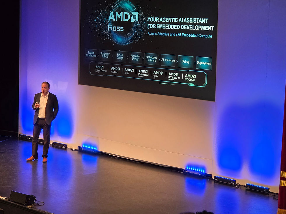
However, the recent announcement of Ross at FPGA Horizons and the subsequent labs made me reconsider and decide that I would take a look at Ross. I did not get a chance to do the lab at either Horizons event, as running the event is a little time-consuming.
So let's start at the beginning with what Ross is and is not. Ross is an agentic AI assistant that is designed to work with a range of frontier and local LLMs to implement not only FPGA and SoC designs but, as attendees at the labs last week discovered, embedded x86 designs as well.
At the heart of Ross are two things. The first is the MCP, which allows the selected LLM to interface with the AMD toolchain and documentation repository. The second is skills, which provide the LLM with the ability to take the correct action. To ensure effective token usage, especially on smaller local models that have a reduced context, the skill file can be read incrementally after the metadata.
If we are using Ross to help with documentation, a vectorised knowledge base uses RAG to provide the necessary information.
It is when we are developing solutions, however, that Ross comes into its own. Using Ross, we are able to perform a range of FPGA design activities, including architecting, design capture, analysis, timing closure and debug. All of these are implemented using the correct skills.
One of the key takeaways from Kirk Saban's keynote at FPGA Horizons recently was that AMD intends to have a much faster update cycle for skills than for the design software.
Let's take a look at creating a simple design targeting the Explorer board.
First, we need to install the MCP and the skills. We can do this either independently on our Linux / Windows system or, if we are using VS Code, we can download and install everything directly, which is what I did. We can then use Copilot to connect to our desired LLM of choice.
With VS Code loaded, I configured the Vivado path for the MCP server to 2026.1, and I was ready to go. To check that it is correctly installed, we can ask the chat window what the installed version of Vivado is and which skills are available.
For this example, I am going to issue the prompt: "Create me a simple MicroBlaze V system with debug and UART to say Hello World when running on the Explorer board."
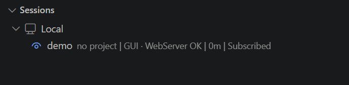
Once this starts running, you will see the session show a local connection on the Vivado bar, with Vivado opening in GUI mode.
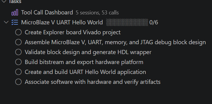
Under the tasks, you will also see a list of tasks that must be undertaken to create the requested design. These include creating the project, targeting the requested board, creating the IP Integrator design, building the bitstream and, of course, creating the application software.
We can, of course, create more complex specifications than this, which detail the FPGA design description if we want to create a more complex FPGA design. However, for this first example, a simple prompt is OK. If we did want to use a detailed specification, we would write this in a Markdown file and use a prompt to say, "Implement the design outlined in the <spec_name>.md file."
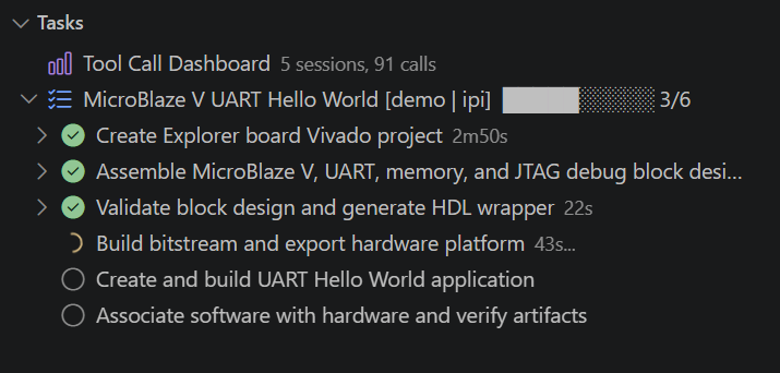
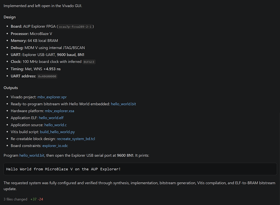
Creating the design took a few minutes, and you can see under the tasks element the progress that is being made.
The block diagram looks exactly as I would have created it, though it only took a few minutes to create. Once it was all ready, I decided to download and test the application on the Explorer board.
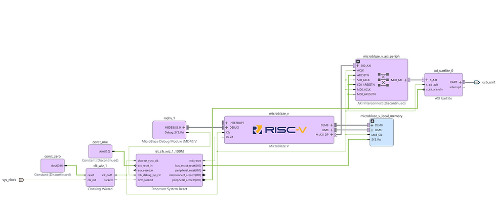
Running it on the board shows the behaviour we would expect from a simple MicroBlaze V system.

Of course, in this example, I have used VS Code. If we want to work outside VS Code, e.g. directly with Claude, Codex or a local LLM, we need to define the location of the downloaded MCP binary for the selected tool. This is simple and can be achieved via the configuration files, as described in the Ross documentation on the Git repo.
I will come back to this in a few weeks and get it set up and running locally on the AMD AI Halo instead of using frontier models. However, in the meantime, there are a lot of other things I want to talk about and demonstrate.
FPGA Journal
Read about cutting edge FPGA developments, in the FPGA Horizons Journal or contribute an article.
Workshops and Webinars:
If you enjoyed the blog why not take a look at the free webinars, workshops and training courses we have created over the years. Highlights include:
Upcoming Webinars Timing, RTL Creation, FPGA Math and Mixed Signal
Professional PYNQ Learn how to use PYNQ in your developments
Introduction to Vivado learn how to use AMD Vivado
Ultra96, MiniZed & ZU1 three day course looking at HW, SW and PetaLinux
Arty Z7-20 Class looking at HW, SW and PetaLinux
Mastering MicroBlaze learn how to create MicroBlaze solutions
HLS Hero Workshop learn how to create High Level Synthesis based solutions
Perfecting Petalinux learn how to create and work with PetaLinux OS
Boards
Get an Adiuvo development board:
Adiuvo Embedded System Development board - Embedded System Development Board
Adiuvo Embedded System Tile - Low Risk way to add a FPGA to your design.
SpaceWire CODEC - SpaceWire CODEC, digital download, AXIS Interfaces
SpaceWire RMAP Initiator - SpaceWire RMAP Initiator, digital download, AXIS & AXI4 Interfaces
SpaceWire RMAP Target - SpaceWire Target, digital download, AXI4 and AXIS Interfaces
Embedded System Book
Do you want to know more about designing embedded systems from scratch? Check out our book on creating embedded systems. This book will walk you through all the stages of requirements, architecture, component selection, schematics, layout, and FPGA / software design. We designed and manufactured the board at the heart of the book! The schematics and layout are available in Altium here. Learn more about the board (see previous blogs on Bring up, DDR validation, USB, Sensors) and view the schematics here.
All words in this blog were written by a human.


