
MicroZed Chronicles: Building the application SW.
- Jun 19, 2025
- 5 min read
Updated: Jun 24, 2025
Last week we examined developing the hardware design in Vivado for the ZUBoard, in this design we configured the processing system correctly for the ZUBoard configuration. That is we configured it clocks, peripherals and its DDR4 timings.

We also added on a GPIO which is connected to the AXI network and to a LED on the board. In this blog we are going to examine creating the application software using Vitis unified development environment.
To get started the first thing we need to do is open Vitis Unified environment and select the workspace. The workspace is where all of our files will be located for the software development on the project. Select Set Workspace on the GUI.

I prefer to keep my workspace close to my Vivado project, but this is just preference.

Once the workspace is set we can start with development of the overall solution. The first thing we need to do is create a platform. A platform defines the underlaying support features necessary to function on the hardware. Within the platform we define the OS type, PetaLinux, stand alone or FreeRTOS. Along with the domain, processor core we wish to use for FreeRTOS and stand alone along with the generation of the boot objects.
From the embedded development tab select create platform component.

This will open a new dialog, which allows you to define the platform name and location.

I left these as default, click next to select the creation flow, we are going to use hardware design and select browse. Here we browse to the XSA which was exported as part of the last blog.

Once the XSA has been selecte click next and we can select the OS type and processor. For this application we will be targeting the standalone application running on the first A53 Core. We will also want the boot artifacts to be generated. We can use these to create not only the deployable boot image but also to debug the application.

The final page is a summary, click finish.

This will create the platform which is now within our workspace.

The next step is to build the platform, click build on the lower left under flow, this might take a few minutes and there should be no errors.

With the platform completed we are now able to create the application, to simplify the project creation we will be using one of the existing templates. Select templates option from the left hand side menu and select hello world.

Click on create application component.

Enter a name and location, I left them as default for this application. On the next tab we need to select the platform which we will be working with.

Leave the domain as standalone

At the summary page click finish.

This will create the hello world application within the Vitis project.

Before we make any changes we will click on build in the lower left, under flow to ensure the project builds successfully – as this is all from templates there should be no issue at all to this point.
You will see this warning, let it always build the platform with the application project to ensure any changes are not missed.

Save this to the workspace preferences.

You should see the application build with no issues.
If you want to explore the application source and the configuration files used in the application you can see these under the hello world folder.

There are several files each with a different roles
Vitis-comp.json is the file which enables the settings for the overall application, using this we are able to change platforms or see information on the platform. We can also make compiler changes to change the optimisation, include libraries etc.

Selecting the compiler changes takes us to the compiler settings which are stored within UserCongif.cmake file.

If we wish to launch the application on hardware we can change the configuration using the launch.json file.

The final element of configuration we might want to change is the settings on the platform and board support package. We can change these by selecting navigate to BSP settings from the application to the application vitis-comp.json file.

Within the settings for the board support package we are able to add in libraries, like LWIP for networking.
To run the demo on hardware we need to connect the ZUBoard to its power source, check the mode switches are set to JTAG and connect the USB JTAG UART to our development PC.

We can then run the application on the board by clicking on the debug option on the flow menu.

This will download the application to the ZUBoard and hold the processor at a breakpoint at the main point of program execution.

We can then run the application by clicking run or single stepping using the debug perspective.

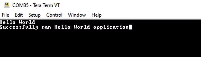
This will show the output in a serial terminal program (115200:N:1)
We have now created , built and run our first application the Zynq MPSoC on the ZUBoard.
In our next blog we will be looking at how we can interact with the LED using the drivers provided by the BSP. They are all very similar to use so a good understanding of one enables to be able to work with them all.
UK FPGA Conference
FPGA Horizons - October 7th 2025 - THE FPGA Conference, find out more here.
Workshops and Webinars:
If you enjoyed the blog why not take a look at the free webinars, workshops and training courses we have created over the years. Highlights include:
Upcoming Webinars Timing, RTL Creation, FPGA Math and Mixed Signal
Professional PYNQ Learn how to use PYNQ in your developments
Introduction to Vivado learn how to use AMD Vivado
Ultra96, MiniZed & ZU1 three day course looking at HW, SW and PetaLinux
Arty Z7-20 Class looking at HW, SW and PetaLinux
Mastering MicroBlaze learn how to create MicroBlaze solutions
HLS Hero Workshop learn how to create High Level Synthesis based solutions
Perfecting Petalinux learn how to create and work with PetaLinux OS
Boards
Get an Adiuvo development board:
Embedded System Book
Do you want to know more about designing embedded systems from scratch? Check out our book on creating embedded systems. This book will walk you through all the stages of requirements, architecture, component selection, schematics, layout, and FPGA / software design. We designed and manufactured the board at the heart of the book! The schematics and layout are available in Altium here Learn more about the board (see previous blogs on Bring up, DDR validation, USB, Sensors) and view the schematics here.
Sponsored by AMD


