
Powering FPGAs Without the Headaches: Evaluating the MCP16701 PMIC
- Dec 26, 2025
- 5 min read
Alongside the design and development of FPGA applications, we also design FPGA- and microprocessor-based boards, for example our tile range, development boards, and tile carrier cards.
One of the key aspects we consider is how we are able to power the FPGA or microprocessor. Powering FPGAs or microprocessors can be a challenge, as we often require low voltages that are very stable while supplying high currents.
Sequencing requirements also come to the fore, with the need to sequence rails in the correct order for power-up and power-down. Failure to comply with these requirements can have some nasty side effects, potentially resulting in damage or loss of part capabilities or features.
I was therefore pleasantly surprised when I came across the Microchip MCP16701, a power management IC intended for FPGA and high-end MCU solutions. Being a PMIC, it can be controlled over I²C, which provides a high level of visibility and configurability of the power solution.
The MCP16701 provides developers with eight 1.5 A buck regulators, which can be connected in parallel to increase the available supply current, along with four 300 mA low-dropout linear regulators and one low-input / low-output LDO controller. The device operates from a 2.7 V to 5.5 V input supply.
As mentioned, the eight buck regulators can be combined in parallel to create higher output currents. With the MCP16701, it is possible to combine up to four outputs, creating a 6 A supply. Both the buck and linear regulators can supply any voltage between 0.6 V and 3.8 V, with the output voltage defined over the I²C interface.
The final LDO controller is intended for use with an external MOSFET to increase power-supply rejection ratio (PSRR) and is designed to provide reference supplies for high-speed SERDES.
Being designed by Microchip, there is obvious built-in support for the PolarFire range of FPGAs, with several signals that can also be used by other FPGAs or MCUs. These include a programmable reset output, which can be assigned a user-defined delay after the completion of all enabled regulators achieving power-OK status, and a simple reset that is asserted once the enabled regulators reach power-OK.
To support wider system requirements, the MCP16701 also includes a watchdog input and output to support MCU features.
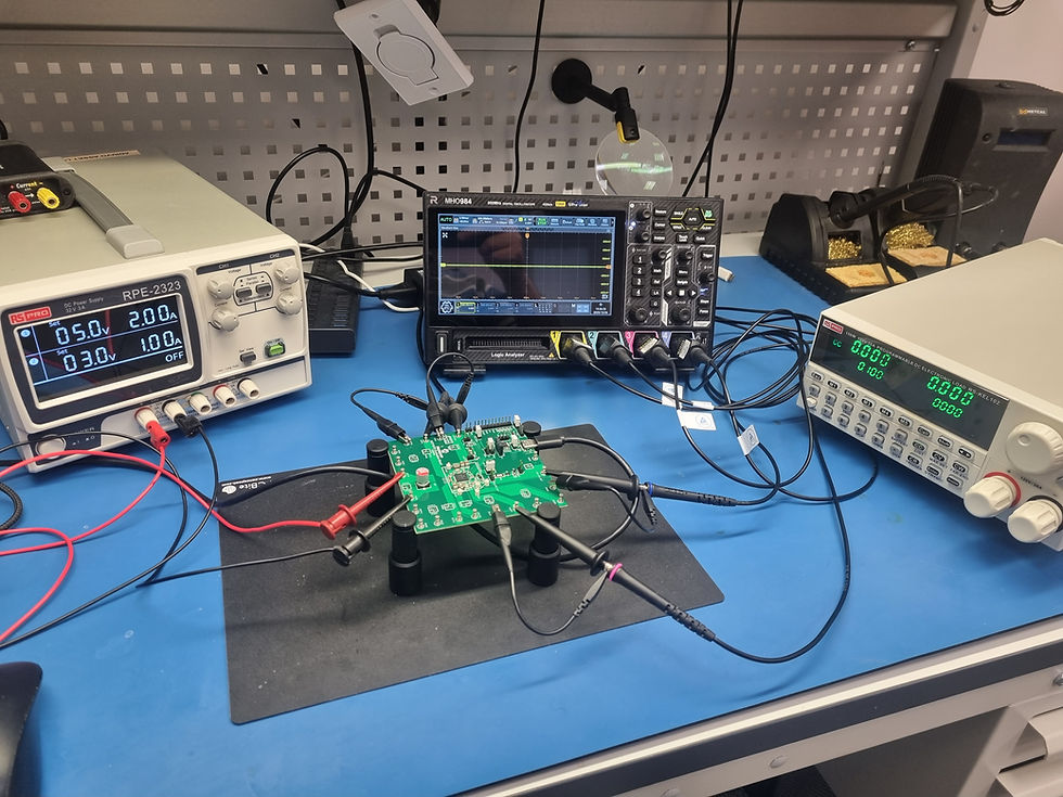
To evaluate the MCP16701, I purchased a development board that contains the device, a USB-to-I²C interface, and breakout connections for many of the buck and linear outputs.
This allows the evaluation board to be connected to a development machine, where the PMIC can be observed and configured over I²C. The outputs can then be connected to an electronic load to observe behaviour under high current conditions.
The evaluation board breaks out several of the bucks as follows:
Buck 1–4 paralleled for a 6 A output at 1.0 V
Buck 5–6 paralleled for a 3 A output at 1.35 V
Buck 7 output at 3.3 V
Buck 8 output at 1.35 V
LDO 1 output at 1.8 V
LDO 2 output at 2.5 V
LDO Controller set for 1.0 V
One of the nice features of the evaluation board is the availability of a host PC application that allows control and monitoring of the PMIC.
When connected, we can initially see the default configuration and status. Some channels are highlighted in red due to them being paralleled.

We can then view the general settings, where the watchdog can be enabled and the reset behaviour defined.

Subsequent tabs are used for configuring the buck regulators and LDOs.


With the board connected to an oscilloscope, I measured the default sequencing of the outputs. This showed clean sequencing, with the 3.3 V rail coming up first, followed by the two 1.35 V rails, and finally the 1.0 V rail.

The output sequence, paralleling of outputs, and output voltages can all be changed using I²C and then stored in non-volatile memory.
The next step was to connect an active load and set it to draw close to the rated current of each rail dynamically.
The first rail tested was the 6 A, 1.0 V output. The results looked very good, especially considering that the only decoupling was on the board and that relatively long cables were used between the evaluation board and the electronic load.

I also had a simple thermal imager available, so I captured an image of the PMIC while it was delivering this power.

The thermal response was reasonable. I also had a JouleScope connected to monitor the input power, which showed the current being drawn, although the capture shown was taken while drawing a steady 6 A load.

Overall, I am impressed with the MCP16701 and think it is a device we will consider using on future projects. However, one word of caution comes to mind from my good friend Dan Binnun, who has noted that highly integrated PMICs can sometimes introduce layout complexity. In such cases, it can be easier to use discrete components, as the associated cost difference is often not significant.
As always, the final decision comes down to engineering experience and determining whether an integrated solution is suitable for the specific application.
FPGA Conference
FPGA Horizons US East - April 28th, 29th 2026 - THE FPGA Conference, find out more here.
FPGA Journal
Read about cutting edge FPGA developments, in the FPGA Horizons Journal or contribute an article.
Workshops and Webinars:
If you enjoyed the blog why not take a look at the free webinars, workshops and training courses we have created over the years. Highlights include:
Upcoming Webinars Timing, RTL Creation, FPGA Math and Mixed Signal
Professional PYNQ Learn how to use PYNQ in your developments
Introduction to Vivado learn how to use AMD Vivado
Ultra96, MiniZed & ZU1 three day course looking at HW, SW and PetaLinux
Arty Z7-20 Class looking at HW, SW and PetaLinux
Mastering MicroBlaze learn how to create MicroBlaze solutions
HLS Hero Workshop learn how to create High Level Synthesis based solutions
Perfecting Petalinux learn how to create and work with PetaLinux OS
Boards
Get an Adiuvo development board:
Adiuvo Embedded System Development board - Embedded System Development Board
Adiuvo Embedded System Tile - Low Risk way to add a FPGA to your design.
SpaceWire CODEC - SpaceWire CODEC, digital download, AXIS Interfaces
SpaceWire RMAP Initiator - SpaceWire RMAP Initiator, digital download, AXIS & AXI4 Interfaces
SpaceWire RMAP Target - SpaceWire Target, digital download, AXI4 and AXIS Interfaces
Embedded System Book
Do you want to know more about designing embedded systems from scratch? Check out our book on creating embedded systems. This book will walk you through all the stages of requirements, architecture, component selection, schematics, layout, and FPGA / software design. We designed and manufactured the board at the heart of the book! The schematics and layout are available in Altium here. Learn more about the board (see previous blogs on Bring up, DDR validation, USB, Sensors) and view the schematics here.


