
Maxim MAX32650FTHR Evaluation Kit
- Mar 31, 2022
- 3 min read
Recently I have been working with a client on a low power AI solution based on microcontroller, for a power management application. One of the candidates examined was the MAX32650FTHR, this is based around an Arm Cortex M4 with FPU, running at 120 MHz. It has 3MB of flash and 1 MB of SRAM and offer a 104 uW/MHz power dissipation, quite a neat little microcontroller.

To examine the processors potential I purchased a couple of MAX32650FTHR Eval boards. Rather nicely the board is compatible with the Adafruit Feather Board standard, so it makes adding additional sensors and interfaces pretty straight forward.
As I sat down to get the board up and running I thought I would keep a record of how I got hello world out of it in a blog to show what software is required and how it is connected together.
When we order the evaluation board we get in the box the following
MAX32650FTHR Eval Board
MAX32625PICO
Serial Wire Debug (SWD) Cable
Two USB A to Micro B cables
The MAX32625 PICO acts as the SW/JTAG programmer / debugger for the MAX32650FTHR, to do this the MAX32625PICO comes loaded with a DAPLink image. One rather nice touch is the MAX32625PICO comes in a compact tin along with the SWD Cable. The Max32625PICO is actually an interesting development board in its own right.


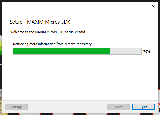
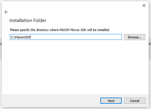
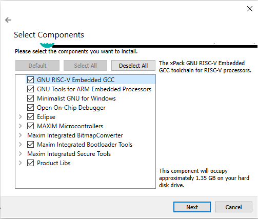
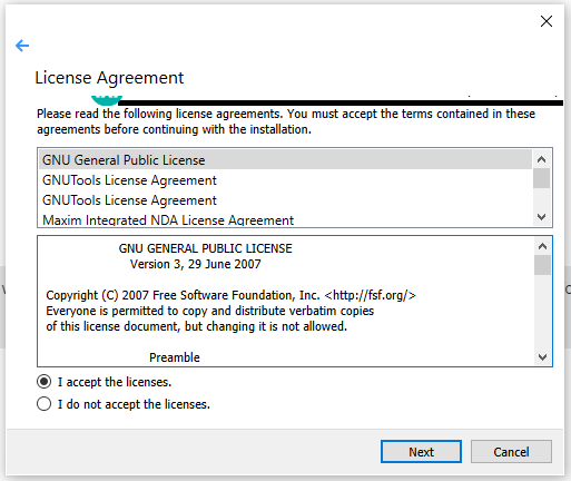
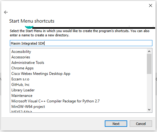
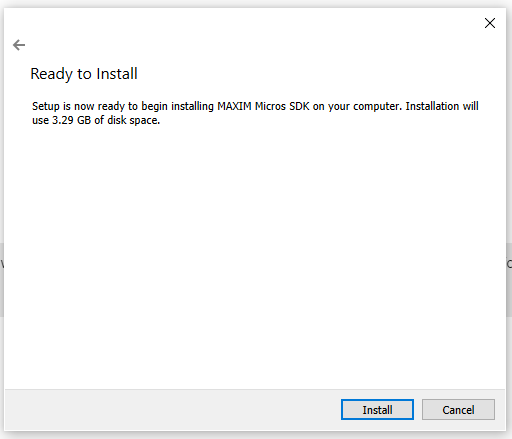
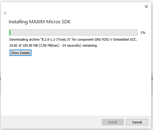
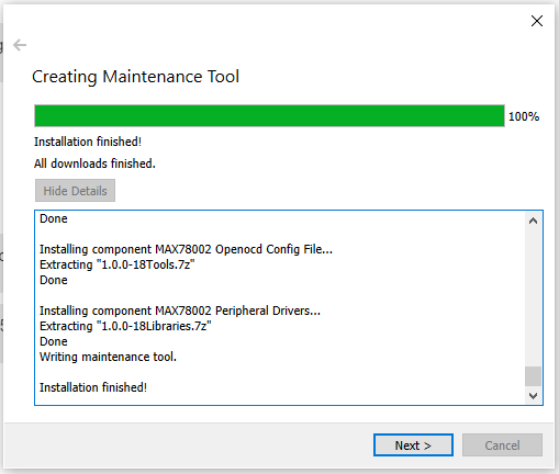
To get started we need to install the Maxim design tools on our development machine, we can install them on Windows, MAC or Linux development systems. Like many SW development environments it is based around Eclipse.
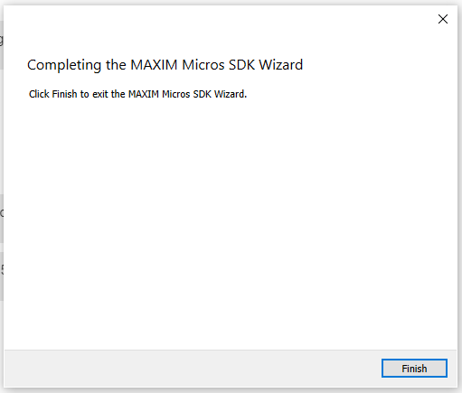
Installation is straight forward, each of the steps for installation can be viewed in the slide show below.


Once the tool is installed we are ready to begin creating our first example application. To do this first we need to open the Maxim SDK and Select the workspace.

With the workspace selected the next step is to create a new application, once MaximSDK loads, close the welcome page and select Maxim Microcontrollers under the project explorer window.

This will open a new wizard to create the application, enter a project name in this case I am calling it hello_world.

With the project name defined click next, this will allow us to select the processor type, board type, select the example application and the debugger - in this case the Max32625PICO.
This will create the basic hello world application, now we are ready to connect the hardware to debug the application.
The first thing we need to do is remove the cover on the MAX32650FTHR boards SWD/DAP connection.


We then need to connect together the MAX32625PICO with the MAX32650FTHR board, to do this we use the SWD cable. The MAX32650FTHR board connector is keyed and the cable only fits one direction. However, the MAX32625PICO is not keyed and as such we need to ensure it aligns correctly. The red strip should align as shown below.

With the two MAX boards connected together and connected over USB to the development machine we are able to debug our application using MaximSDK.

We can select the RUN/Debug elements as desired from the drop down menu in the tool bar, double check we have built the application. If not hit the hammer on the tool bar to build the binary and download the application to the MAX32650FTHR.

If you select Debug the application will halt paused ready for single stepping for running.

When the application downloads and halts awaiting execution, we can open a serial terminal program select a baud rate of 115200, no parity and one stop bit.
Running the application you should then see output in the terminal like below

Now we have a development environment we can use with the MAX32650FTHR and we can start on the development of the application.
More importantly now I have written this up I will not forget the steps involved when I come back to look at it!


